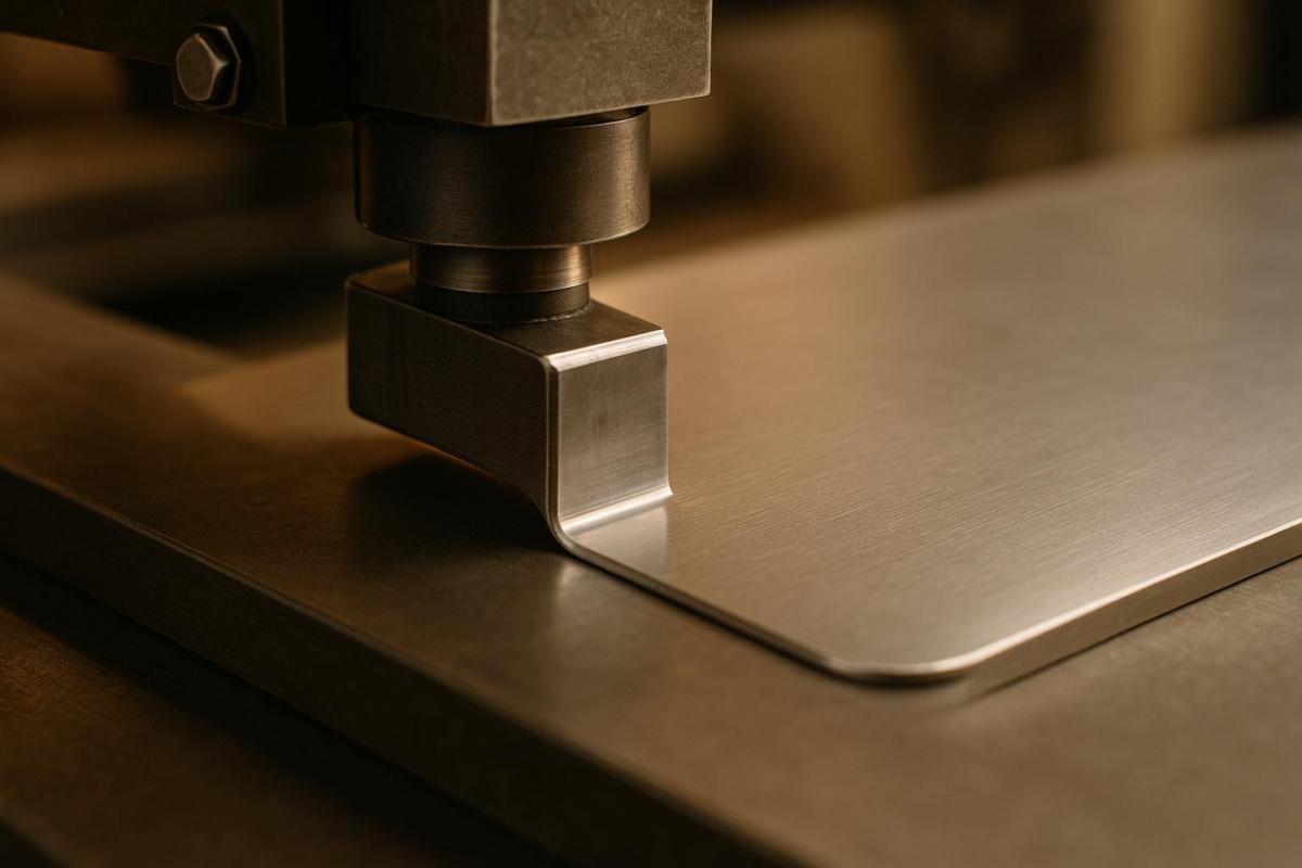
The corner radius in die-cutting design directly impacts production efficiency and product quality. Here’s what you need to know:
- What is it? The corner radius is the curve at the corner of a die-cut shape, measured as the radius of an imaginary circle.
- Why does it matter? Proper corner radii reduce wear on tools, prevent material tearing, and improve adhesion and durability.
- Key Recommendations:
- Minimum corner radius: 1 mm (0.0394 inches); 3 mm (0.118 inches) is often better.
- For thin materials, use at least 0.031 inches to avoid cracking.
- Match or exceed the material’s thickness for internal corners.
- Design Tips:
- Use vector software for precision.
- Account for tool tolerances (±0.010 inches) and material elongation during cutting.
- Keep at least twice the material thickness between slots to prevent tearing.
Quick takeaway: A well-planned corner radius improves efficiency, reduces costs, and ensures a durable final product. Let’s dive into the details!
Design Guidelines for Corner Radius
Material-Specific Radius Sizes
Choosing the right corner radius depends heavily on the material’s properties and thickness. Here’s a quick reference:
| Material Type | Recommended Minimum Radius | Special Considerations |
|---|---|---|
| Thin Paper | 0.031" | Helps prevent tearing and cracking |
| Cardstock | 0.031" | Thicker cardstock may require a larger radius |
| Rigid Plastic | ≥ 1 mm (≈0.04") | Larger radii reduce stress points |
| Flexible Materials | 0.031" or greater | Accommodate elongation (over 15%) during cutting |
By following these material-specific guidelines, you can avoid common issues like tearing, cracking, or stress points.
Preventing Corner Issues
To minimize corner-related problems, stick to these essential practices:
- Internal Corners: Always use a minimum radius of 0.031 inches. This reduces material stress and extends the lifespan of die-cutting tools. For thicker materials, the radius should match or exceed the material’s thickness.
- Spacing Between Slots: Maintain a distance of at least twice the material’s thickness to avoid tearing.
These adjustments not only improve the design but also enhance the durability of the final product.
Corner Radius in Design Software
When designing corner radii in software like Adobe Illustrator, precision is key. Here’s how to get it right:
- CNC-Manufactured Dies: These dies typically have a tolerance of ±0.010 inches. Set corner radius values accurately to stay within this tolerance.
- Internal Corners: Increase the radius by 0.02"–0.05" to account for cutter movement during manufacturing.
- Properties Panel: Use this tool for exact measurements rather than relying on visual adjustments with the Corner Widget. This ensures your design meets manufacturing standards.
For more intricate designs with multiple radius adjustments:
- Select all corners that need the same radius.
- Enter the exact measurement in the Properties panel.
- Double-check all measurements for accuracy.
- Export the design in a vector format for production.
While straight exterior edges and square corners can simplify the die-making process and reduce costs, they should only be used if they don’t compromise the product’s structural integrity.
Following these practices ensures your design meets technical requirements while maintaining quality and durability.
Technical Requirements
Material Thickness Guidelines
The thickness of your material plays a key role in determining the minimum corner radius for your design. As a general rule, the corner radius should be at least equal to the material’s thickness. For very thin materials – those with a thickness under 0.031 inches – a minimum radius of 0.031 inches is recommended to avoid cracking. Ideally, aim for a corner radius approximately twice the material’s thickness for optimal results.
For example, if you’re working with 0.030-inch material, use a minimum radius of 0.031 inches, but an optimal radius would be closer to 0.060 inches.
Here’s a quick reference table to guide your corner radius selection based on material thickness:
| Material Thickness | Minimum Corner Radius | Optimal Corner Radius |
|---|---|---|
| Up to 0.031" | 0.031" | ~2× material thickness |
| 0.031" – 0.060" | Equal to material thickness | ~2× material thickness |
| Greater than 0.060" | Equal to material thickness | 2× material thickness |
Note: Specific material properties and die-cutting methods may require adjustments to these guidelines.
Once you’ve established the appropriate radii, ensure your dielines are precisely defined to meet these standards.
Dieline Setup Steps
Start by defining the finished cut line, then add the necessary specifications. Include a standard bleed area of 0.125 inches beyond the cut line to ensure that colors and images extend fully to the edge.
For designs with multiple corner radii or intricate details, follow these steps:
- Use vector-based design software to create precise paths.
- Extend your artwork 0.125 inches beyond the cut lines, and maintain a 0.125-inch safety margin inside the cut line to protect key elements.
- Clearly label the corner radius measurements on your design.
"Most die tools are manufactured using CNC routers with tolerances of ±0.010 inches. When working with elastomeric materials, expect potential elongation of more than 15% during the cutting process".
After setting up your dielines, consider the precision limits of the tools to fine-tune your design.
Tool Precision Limits
The precision of your tools directly impacts the execution of corner radii. CNC-manufactured dies typically operate within a tolerance of ±0.010 inches, which should guide your design adjustments.
For internal corners, keep these factors in mind:
- Add 0.02 to 0.05 inches to account for tool movement and material elasticity. Standard square punches, for instance, increase incrementally by 0.015 inches.
- Be aware of potential elongation during the cutting process.
- Maintain a spacing of at least twice the material thickness between slots to ensure structural integrity.
Working with Print Providers
File Preparation Steps
When submitting files to print providers, ensure they are production-ready. Use vector-based software like Adobe Illustrator or CorelDRAW to create dielines, and save them in formats such as PDF, AI, or EPS. To avoid confusion, place dielines on a separate layer and assign a distinct spot color for easy identification.
Here are the key file requirements:
| Element | Specification | Notes |
|---|---|---|
| Corner Radius | As specified in design guidelines | Adjust to account for material thickness |
| File Format | Vector-based | Acceptable formats: AI, EPS, PDF |
| Dieline Layer | Separate layer | Use a spot color for visibility |
| Font Treatment | Convert all text to outlines | N/A |
If your files need further refinement, expert support is available to assist with adjustments.
Professional Support Options
Miro Printing & Graphics Inc. offers specialized support to ensure your designs are ready for production. Their services include:
- Pre-press file review to optimize your designs for printing.
- Recommendations on materials tailored to your project needs.
- Assistance with intricate die-cutting patterns.
- Sample cuts to validate designs before full production.
Production Process Tips
To achieve the best results, align your designs with the production process by keeping these tips in mind:
- Material and Tooling: Consider material properties, such as elongation (over 15% for elastomeric materials), and the CNC router’s tolerances, which are ±0.010 inches. These factors are crucial when specifying corner radii.
- Standard Specifications: Opt for standard punch sizes and corner radii to minimize costs and simplify production.
- Quality Assurance: Collaborate with Miro Printing & Graphics Inc. to fine-tune your design. Their team ensures your project meets aesthetic and functional standards while staying compatible with their equipment.
sbb-itb-ce53437
Summary
Main Guidelines Review
When working on die-cut designs, keep these essential specifications in mind:
| Design Element | Specification | Key Consideration |
|---|---|---|
| Internal Corners | Minimum 0.031" (0.8 mm) radius | Helps prevent cracking or splitting of material |
| External Edges | Straight where possible | Allows for cost-efficient common ruling |
| Feature Spacing | 2x material thickness | Ensures structural integrity |
| Tool Tolerance | ±0.010" | Compensates for material properties |
For elastomeric materials (those with over 15% elongation), additional tolerances are necessary to avoid hour-glassing effects.
Getting Started
Start by assessing the material requirements and design constraints for your project. The design team at Miro Printing & Graphics Inc. is available to help fine-tune your dielines, ensuring your die-cut projects meet both aesthetic and structural needs while adhering to manufacturing standards.
To save on tooling costs, adjust internal radii by 0.02"–0.05" and stick to standard punch sizes (in increments of 0.015"). Be sure to account for the unique properties of your chosen material when finalizing measurements.
For expert assistance, contact Miro Printing & Graphics Inc.. Their pre-press review service is designed to spot potential issues early, helping you achieve the best possible results for your specific application.
LightBurn Quick Tips: Corner Radius
FAQs
How can I choose the right corner radius for different materials in die cutting?
When it comes to die cutting, the perfect corner radius largely depends on the material you’re working with and the result you’re aiming for. Sharp corners are usually a no-go – they can cause tearing or uneven cuts. Instead, opting for a rounded corner radius can lead to smoother edges and improve the overall durability of your piece.
Here’s a quick rule of thumb: softer materials like paper or thin cardstock can handle smaller radii, while tougher or thicker materials – think plastic or heavy cardstock – typically need larger radii to avoid cracking or other damage. Testing with sample cuts or consulting a professional can help you nail down the right radius for your specific project.
Need help? Miro Printing & Graphics Inc. offers tailored guidance and expertise in die cutting and design, ensuring your project is crafted with precision and care.
What problems can occur with incorrect corner radii in die cutting, and how can they be avoided?
Incorrect corner radii in die cutting can cause problems like tearing, uneven edges, or unnecessary wear on the cutting dies. For example, sharp corners can act as stress points, leading to material tearing during the cutting process. Similarly, using radii that are too tight or poorly chosen can make it harder to achieve clean and precise cuts.
To avoid these issues, it’s crucial to select corner radii that align with the material and design requirements. Rounded corners with an appropriate radius can result in smoother cuts and extend the life of your dies. Partnering with a skilled print and die-cutting service, such as Miro Printing & Graphics Inc., can help ensure your designs meet the right specifications for the best possible outcome.
Why should tool tolerances and material flexibility be considered when designing corner radii for die cutting?
When working on corner radii for die cutting, it’s crucial to consider tool tolerances and material flexibility to achieve clean and accurate cuts. Die-cutting tools have their limits when it comes to handling sharp or highly detailed corners. Adding appropriate radii not only reduces wear and tear on the tools but also ensures smoother production. On top of that, materials can stretch or deform slightly during the cutting process, which might alter the final shape if these factors aren’t taken into account. By addressing these details in your design, you can improve precision and help your die-cutting tools last longer.
Related posts
- How Die-Cutting Impacts Waste Reduction
- How to Create Die-Cut Templates for Printing
- How to Prepare Files for Die-Cutting and Laser Cutting
- How Digital Die-Cutting Works for Packaging
https://app.seobotai.com/banner/banner.js?id=6825535f0209458b3ff35ace
